ISO 9001:2008 Enterprise |
|
Special Focus |
| In the News News Index  Agnee Registered as Vendor with Defense Details |
| Agro Engineers (ISO 9001:2008 Enterprise) F-557, Indraprastha Industrial Area, Kota - 324005, Rajasthan, INDIA. Telephone:+91-744-2490773 Contact Us |
D&B D-U-N-S® Number |

Home | About Us | Contact Us | Complaint | Warranty
|
|
|
||||
Type of Couplings |
|||||
| There are two
basic classes of couplings:- 1. Rigid Coupling 2. Flexible Couplings Rigid Slip Couplings |
|||||
| |||||
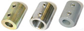
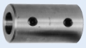
| Types of Rigid
Couplings:- 1.1 Sleeve or muff coupling 1.2 Clamp coupling 1.3 Flange coupling 1.1 Sleeve or muff coupling |
|||||
| |||||
| 1.2 Clamp coupling Clamp coupling is sometimes called a compression coupling or a ribbed coupling. Clamp coupling is a modification and a improvement of the sleeve coupling. This coupling is made in two parts which are machined to fit the shaft and are finished off around the periphery and on both ends. The two halves of the coupling are clamped tightly against the surface of the shaft ends by through bolts and the entire torsional moment is transmitted entirely by friction. 1.3 Flange coupling A flange coupling usually applies to a coupling having two separate cast iron flanges. Each flange is mounted on the shaft end and keyed to it. The faces are turned up at right angle to the axis of the shaft. One of the flange has a projected portion and the other flange has a corresponding recess. This helps to bring the shafts into line and to maintain alignment. The two flanges are coupled together by means of bolts and nuts. The flange coupling is adopted to heavy loads and hence it is used on large shafting. The flange couplings are of the following types:- a) Unprotected type flange coupling b) Protected type flange coupling c) Marine type flange coupling a) Unprotected type flange coupling:- In an unprotected type flange coupling each shaft is keyed to the boss of a flange with a
counter sunk key, and the flange are coupled together by means of bolts. Generally, three, four or six bolts are used. The keys
are staggered at right angle along the circumference of the shafts in order to divide the weakening effect caused by key ways.
| |||||
|
|
|
||||