ISO 9001:2008 Enterprise |
|
Special Focus |
| In the News News Index  Agnee Registered as Vendor with Defense Details |
| Agro Engineers (ISO 9001:2008 Enterprise) F-557, Indraprastha Industrial Area, Kota - 324005, Rajasthan, INDIA. Telephone:+91-744-2490773 Contact Us |
D&B D-U-N-S® Number |

Home | About Us | Contact Us | Complaint | Warranty
|
|
|
||
Technical SpecificationsLoad Carrying Capacity Of A Bearing |
|||
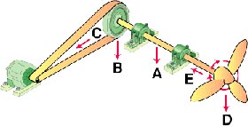
| The example shows a shaft mounted fan
driven by a belt and powered by a motor. Radial loads originate from:- A. Weight of the shaft B. Weight of the pulley C. Tension of the belt D. Weight of the propeller E. Propeller rotation Axial loads originate from the wind (E) induced by the propeller rotation. Combination loads are the result of both radial load (s) and axial load (s) being combined and exerted on a single bearing. To ensure a define load carrying capacity of ball and roller bearings for a given application, it is essential to have a clear idea about the running speed, the size and direction of the loads and the designed expectation of life. The magnitude of load is always influenced by the running speed. For every bearing number its maximum load carrying capacity is specified, corresponding to various running speeds. This load carrying capacity is considered to be valid only for the bearing having normal dimensional and running accuracy, proper methods of lubrication and a speed which yields a life expectance of approximately 5000 running hours. |
|
||
|
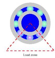
The Load Zone and Contact Points When a bearing is supporting a radial load, the load is distributed through only a portion of the bearing—approximately one-third (1/3)—at any given time. This area supporting the load is called the bearing load zone. Radial ball bearings are probably the most widely used and most recognized ball bearing. These bearings have one row of balls (referred to as a single row), that revolves around the ball path. This feature provides another name for the bearings; they are commonly called deep groove ball bearings. Although designed to primarily carry radial loads, a radial ball bearing’s raceways are deep enough that it can also carry reasonable thrust loads. (However, if thrust loads are excessive, an alternative type of bearing should be considered.) |
|
||
|
|
|